The rail-crane methodology
Most elevated infrastructure is built from the ground up — access roads, lay-down yards, mobile cranes positioned alongside. The SBC is built from the rails up. The rail crane runs on the existing freight line that the SBC is built above, lifting prefabricated pylon legs, longitudinal beams, deck sections, and tensioning elements into position. The crane progresses bay by bay along the corridor, with construction trailing behind it.
This is the methodology the patent specifications describe. Each step below corresponds to specific architectural primitives covered by the five-patent ATS Family. The patents protect the IP. The sequence shows how it actually goes together.
Before Step 1 — foundation preparation. The pylon footings, drilled core, and integrated foundation are completed first by a separate crew working ahead of the rail crane. This is the work covered by Patents #1 (Foundation Core), #2 (Integrated Foundation), and #3 (Foundation Drilling System). Once the foundations are cast and cured, the rail-crane sequence below begins.
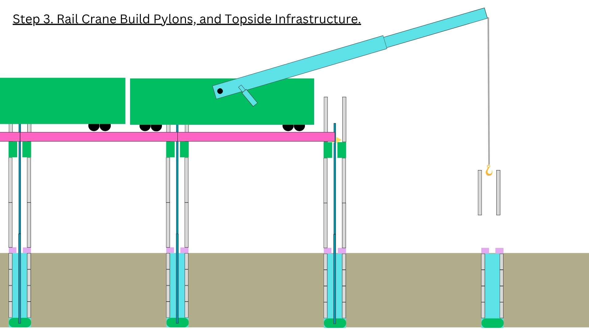
The rail crane — mounted on a flatbed wagon riding the existing freight line — lifts prefabricated pylon legs into position above the prepared foundations. Each leg is hollow steel tube with the ATS tension element threaded through its centre, ready for tensioning. Two legs per pylon, every 25 metres. The four-leg pylon module is established at this step.
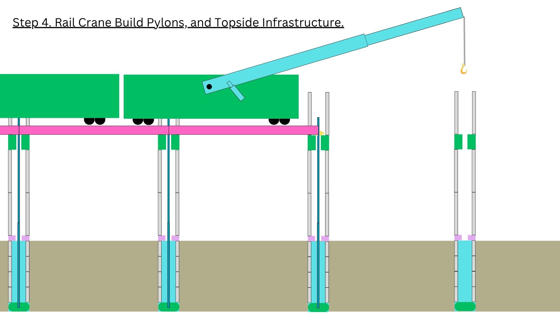
The crane indexes forward to the next pylon position. Another set of legs is lifted into the prepared footings ahead of the existing structure. The pattern continues bay by bay along the corridor — the pylons rise behind the crane as it advances.
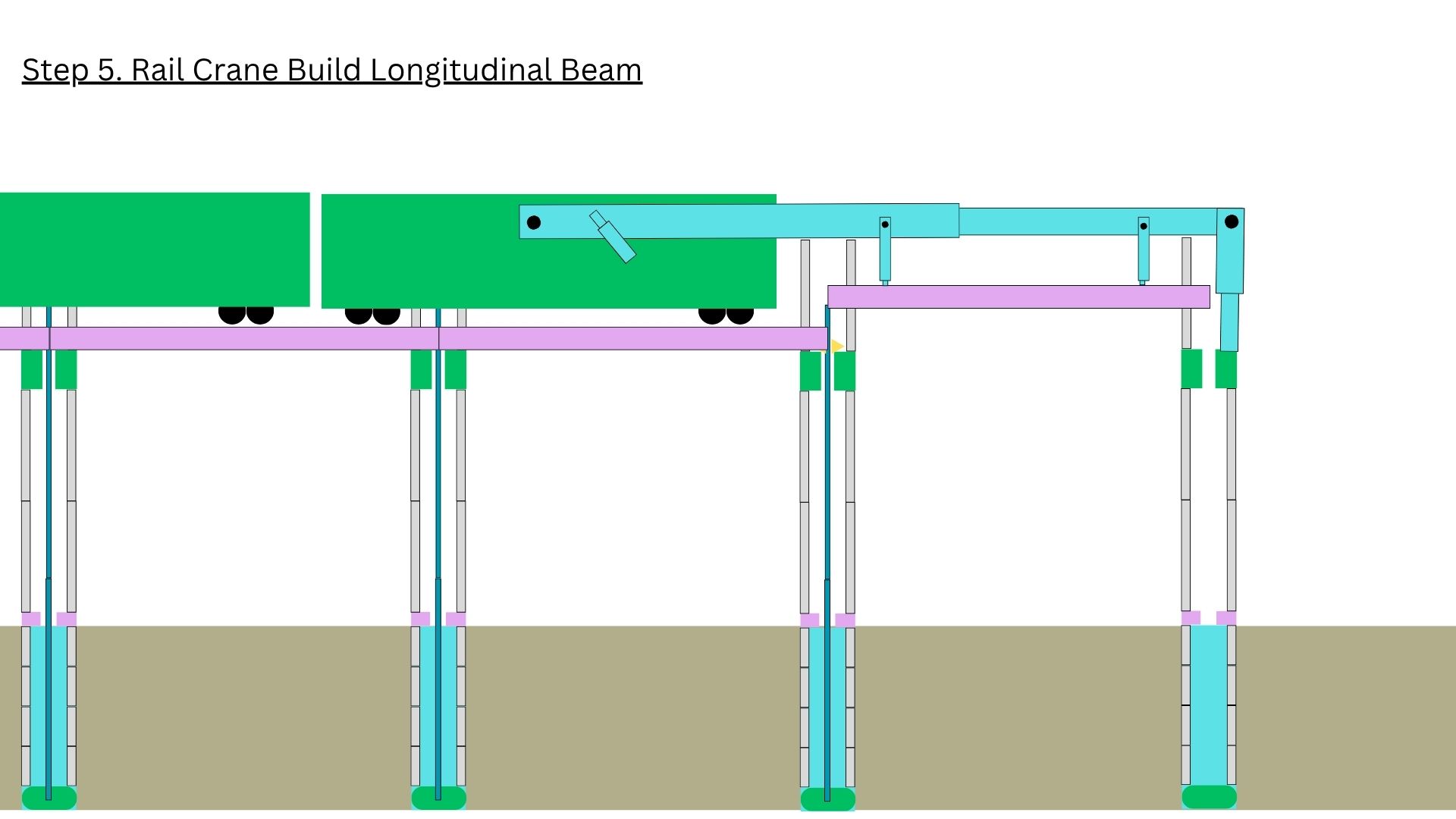
A longitudinal beam is lifted onto the capped pylon legs. The beam is the precast structural element that ties pylon-pair to pylon-pair along the length of the corridor and forms the bearing surface for the freight deck above.
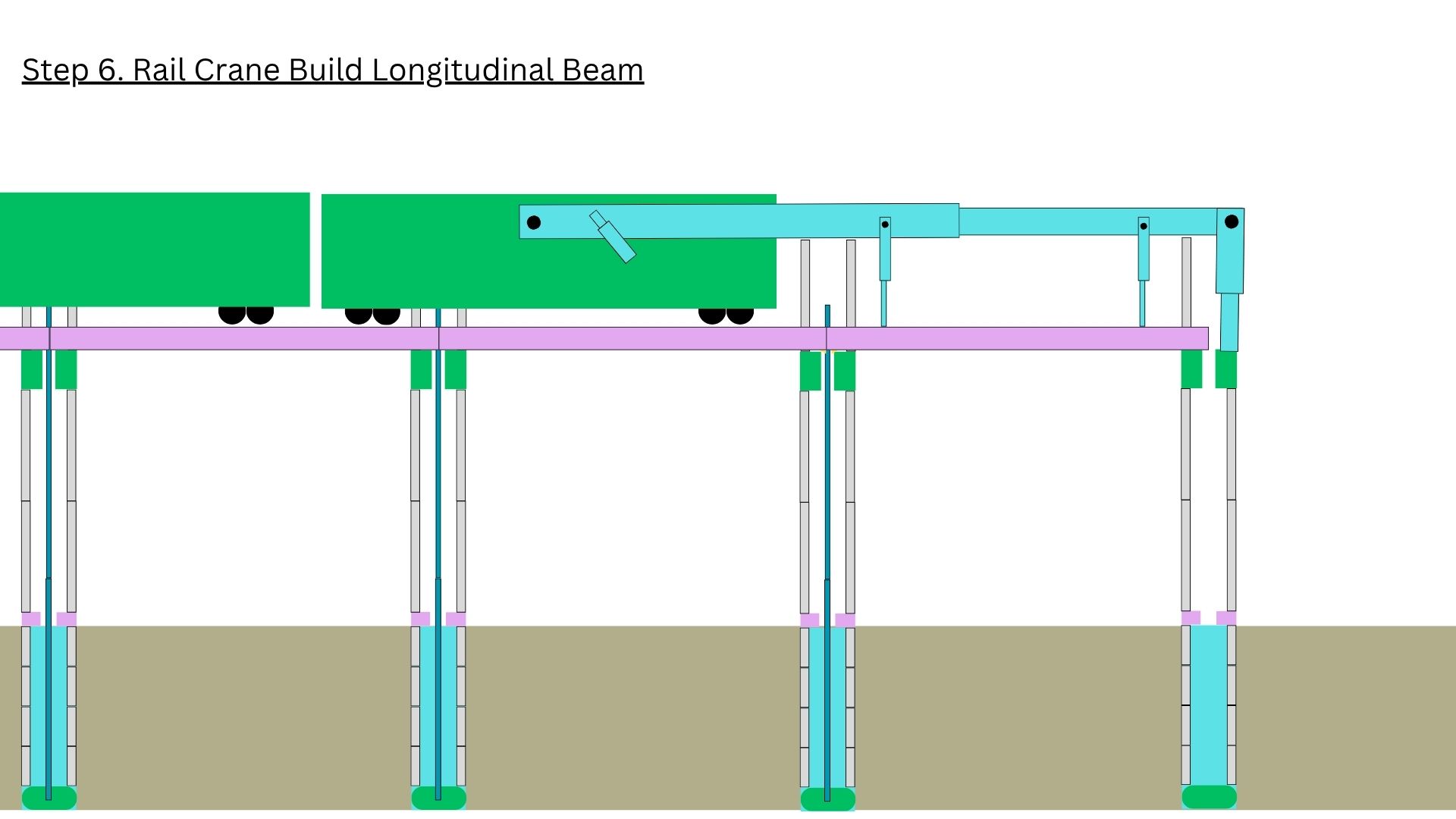
The crane indexes forward and places the next longitudinal beam segment. The beams are designed to interlock at pylon centres, transferring load progressively along the structure.
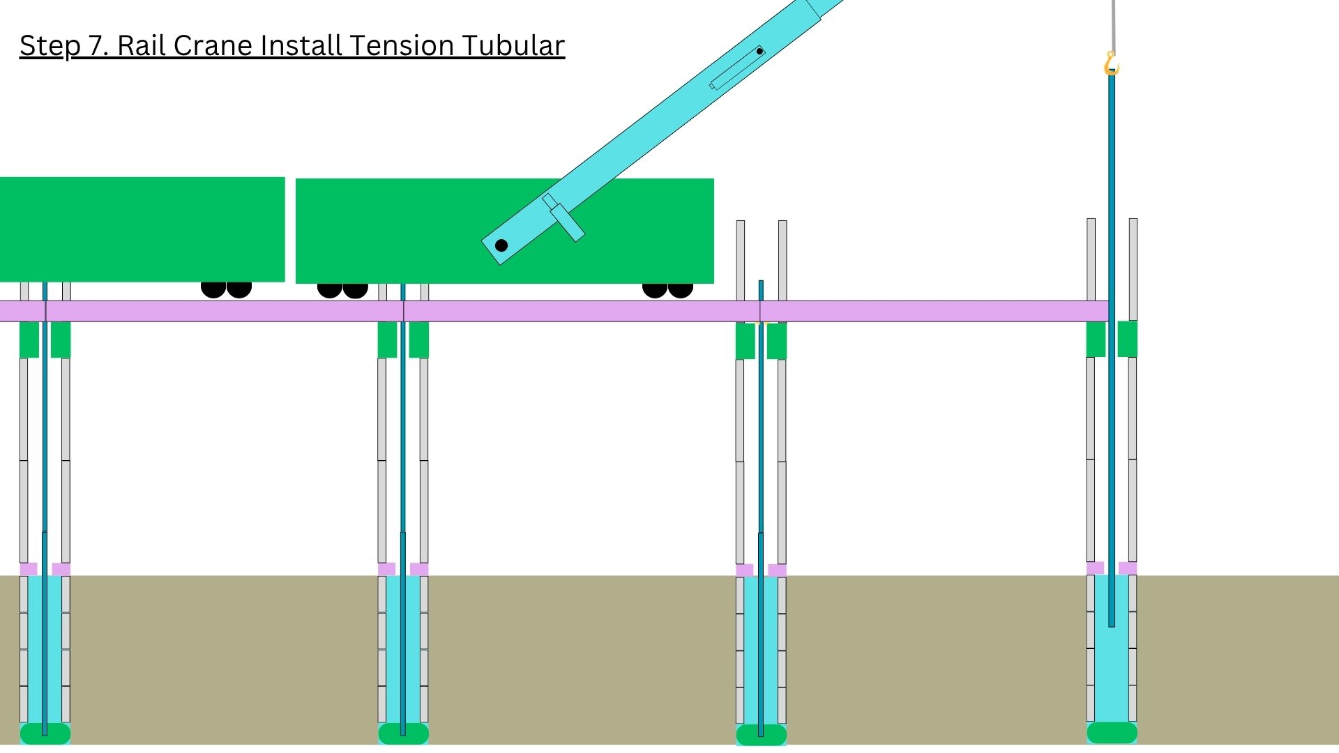
The tension tubular — the heart of Patent #4’s Renewable Tension Element — is lowered into position. This is the single most novel architectural primitive in the ATS family: a high-tensile member that can be installed, tensioned, de-tensioned, and replaced over the operational life of the structure without compromising the load path.
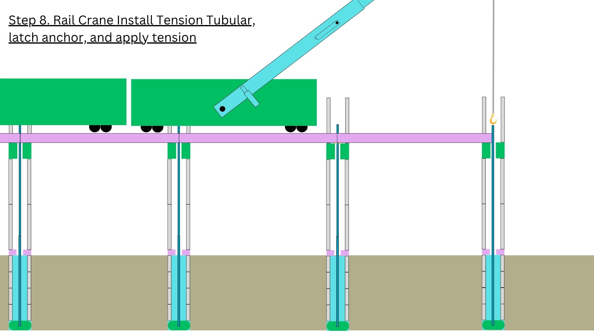
The tension tubular is secured by a latch anchor at the base and tension is progressively applied. The structure becomes a tensioned framework — the ATS architectural primitive in its loaded state. Load is shared between compression in the legs and tension in the central element. This is what the patent protects.
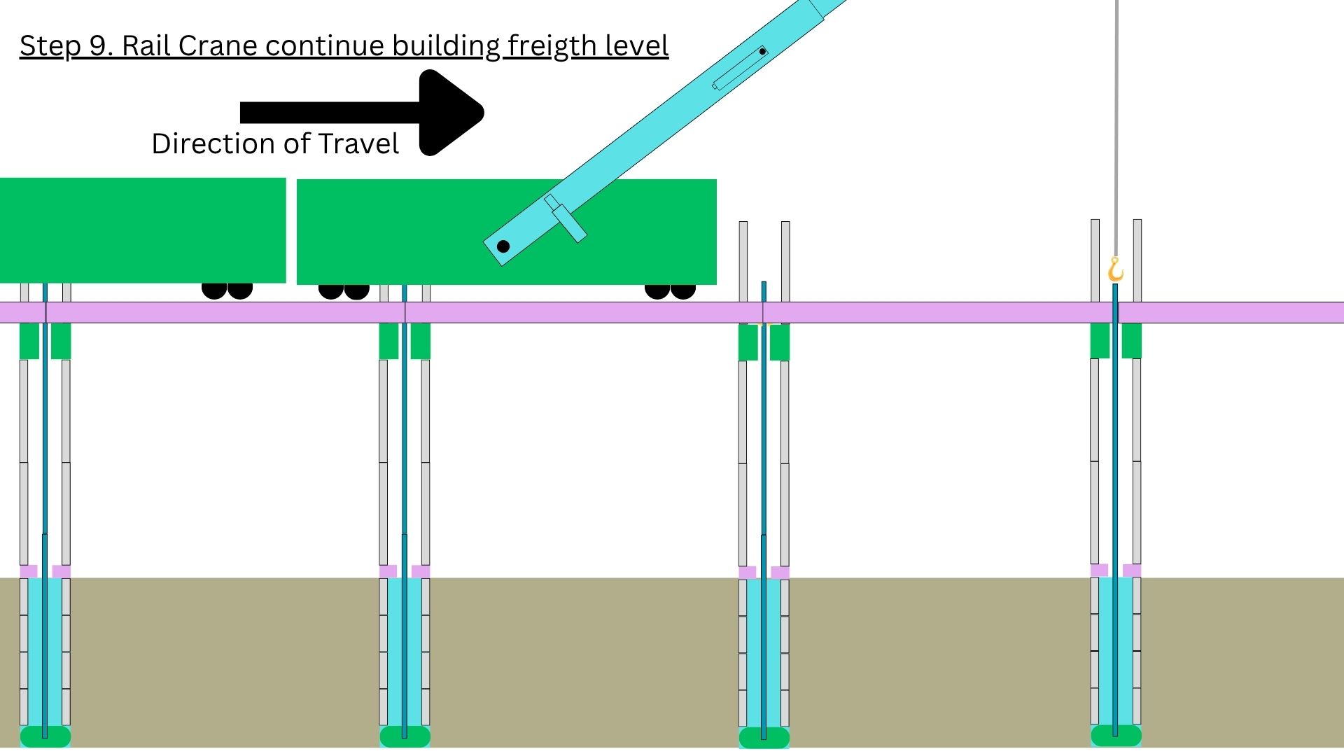
With the pylon framework tensioned and stable, the freight-level deck is built out forward. The crane progresses along the corridor, placing precast deck segments onto the longitudinal beams. The freight rails run on top of these deck segments. The freight line is operational at the end of this step — this is when revenue starts.
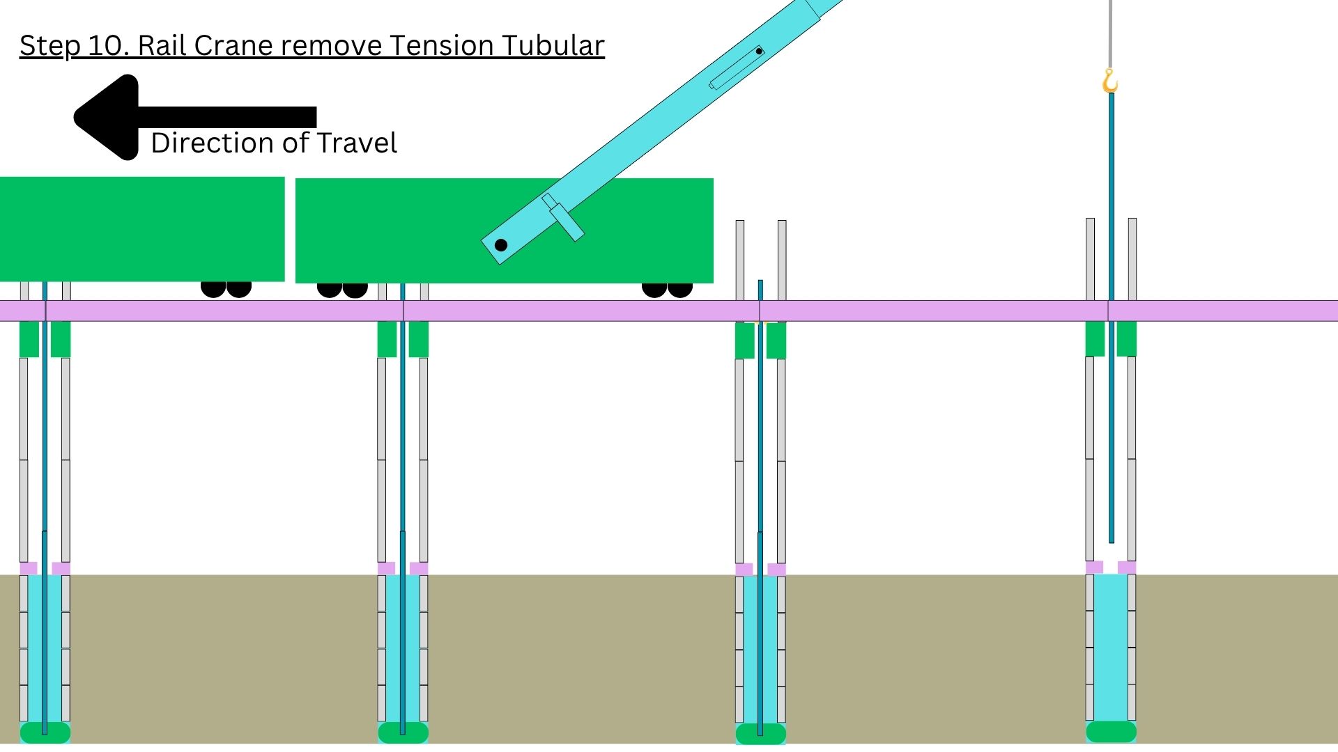
The renewable aspect of the tension element in action. Once the structure has set and the freight deck has stabilised the load, the tension tubular can be retrieved and re-used downstream. The same tubular element can install, tension, hold, and release across multiple spans — capital efficiency by design. This is what makes the tension element “renewable” in the patent name.
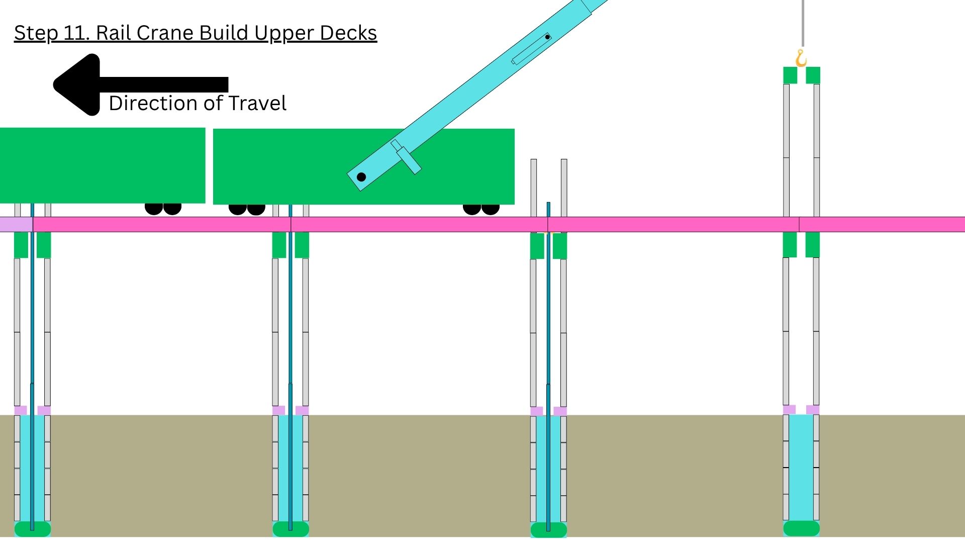
With freight operational and the structure proven, work begins on the upper deck levels. This is where the SBC’s multi-service architecture is realised — maglev passenger above, services (HVDC, water, gas, hydrogen, fibre) integrated into the deck structure. The freight line below remains operational throughout this work.
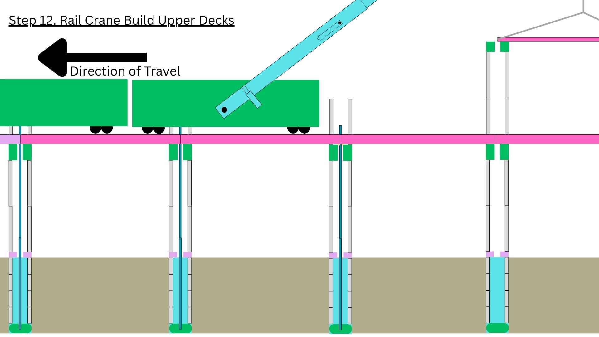
The crane advances and places the next upper-deck segment. The construction self-platforms — the freight deck below becomes the working surface for assembling the maglev deck above. No separate scaffolding. No construction roads. The structure builds itself.
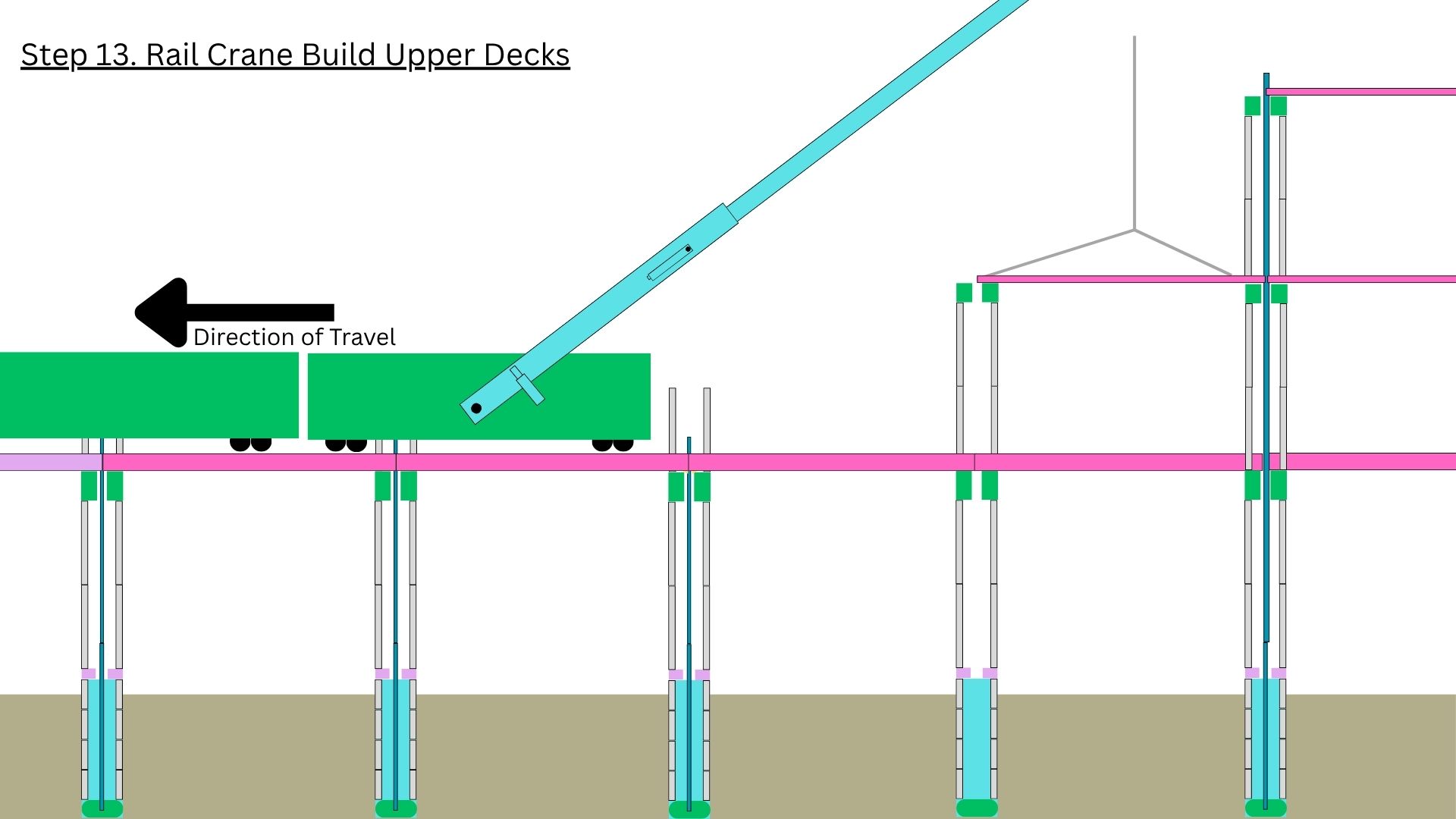
The multi-deck topside takes shape. Successive levels carry different services — the architecture is modular and the deck count can be specified per corridor. Phase 0 design is two-deck (freight + maglev). National-network corridors will run higher-density topsides where the demand justifies it.
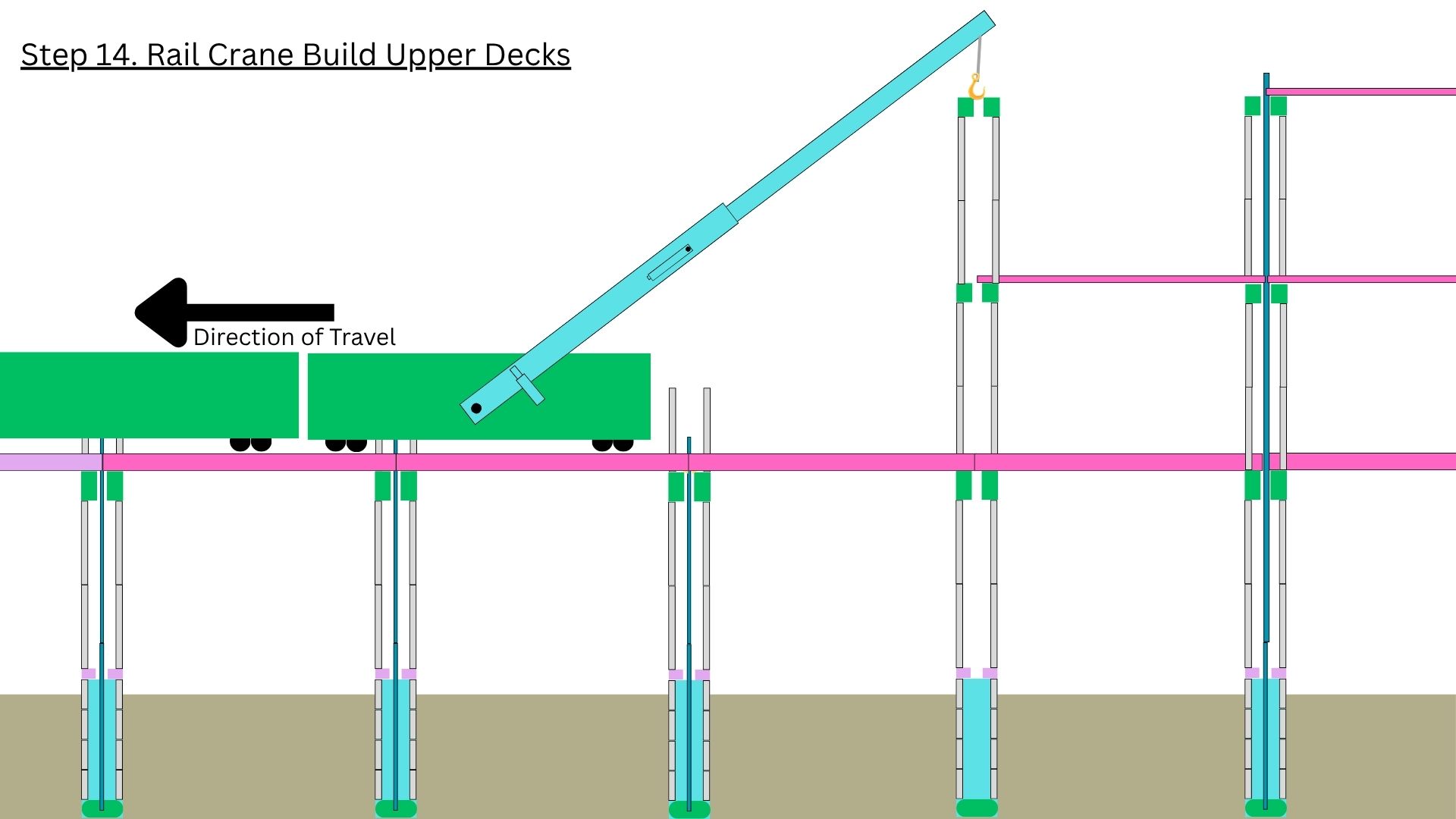
Final upper-deck segments installed. The pylon legs and longitudinal beams are in place at full design height — but the upper level is not yet tensioned. The same renewable tension element process that locked the lower level (Steps 5–6) now repeats at the top.
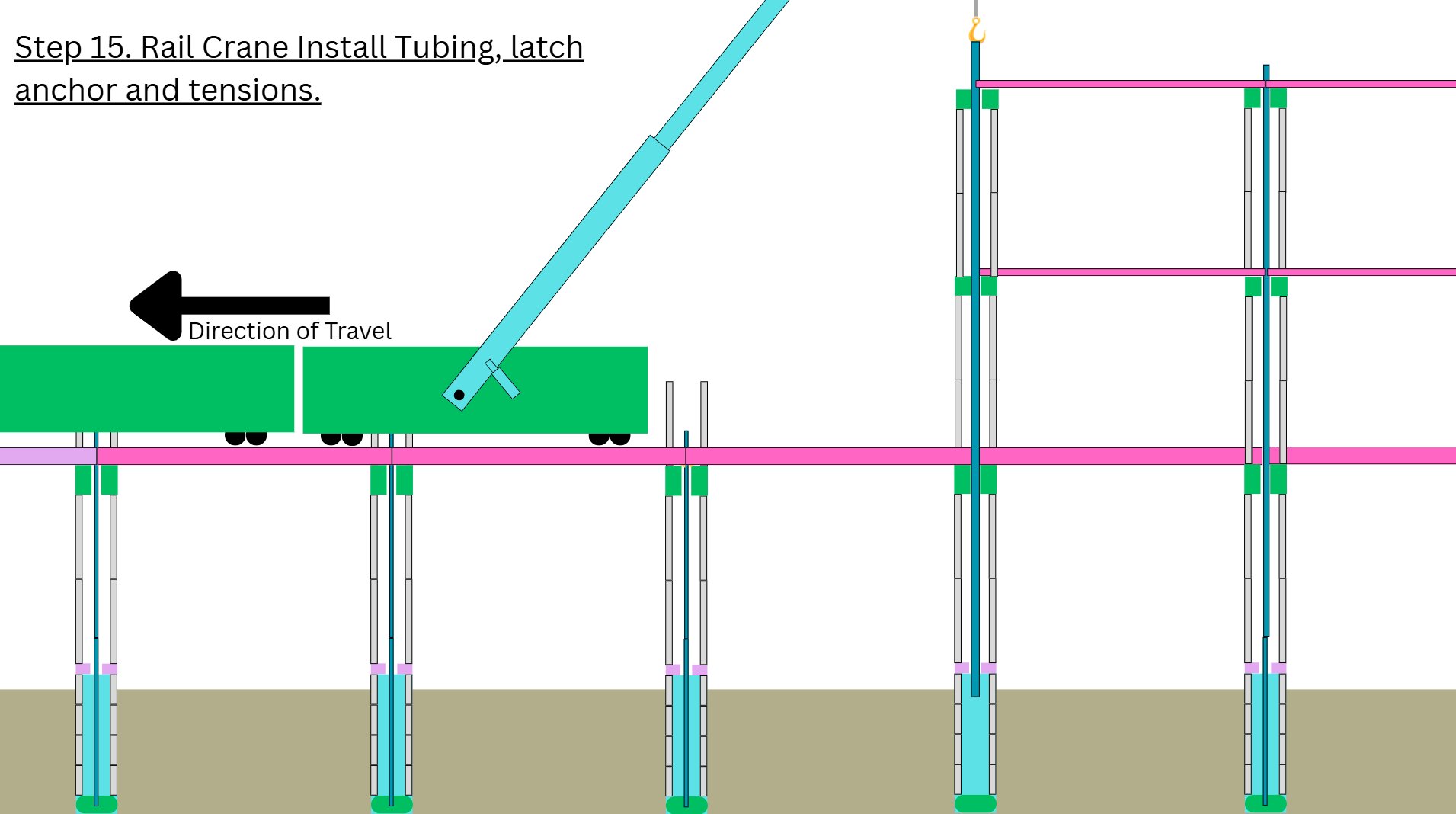
The renewable tension element is installed at the upper level, the latch anchor is engaged, and tension is applied. The same architectural primitive works at every level of the multi-deck pylon — the patent #4 methodology scales vertically across the full structure. The tubular can later be retrieved and re-used downstream, just like the lower-level cycle. The structure is now complete and ready for the crane to advance to the next bay. The methodology repeats end-to-end along the corridor — a continuous, repeatable, manufacturing-style construction pattern that delivers the per-kilometre cost the SBC business case relies on.
The patent record & the engineering
The construction sequence above is the practical embodiment of the five-patent ATS (Anchor Tension System) Family. Patents protect the architectural primitives. The Pylon Design specification is published as defensive prior art. The Master Development Document explains the corridor strategy. All four canonical SBC documents and the patent record are publicly available.